DK-TM4C123G is an Cortex-M4F based MCU from TI, it provides good performance and advanced integration. It is positioned for cost conscious applications requiring significant control processing and connectivity capabilities. On its peripheral support, TM4C123G supports 4 SSI ports.
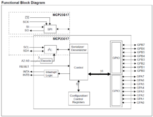
MCP23S17is a 16 bit IO expander with SPI serial interface which can run up to 10MHz. For its IO, MCP23S17 has two 8 its ports: Port A and Port B, which can be configured as either Input or Output independently. There two ports can also be configured to operate together. In addition, it has an interrupt line for each port to raise an interrupt to the CPU on change or Pin changes. It also allows CPU to reset it via a RESET line. Pleas see below graph for illustration.

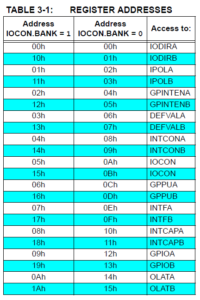
MCP23S17 contains 22 individual registers that can be addressed through the SPI interface:

It has the ability to operate in either BYTE or SEQUENTIAL mode (by using ICON.SEQOP register). BYTW mode disables automatic Address Pointer incrementing, which gives the ability to continuously access the same address by providing extra clocks. This is useful for polling the GPIO register for data changes or for continuously writing to the output latches. SEQUENTIAL mode enables automatic address incrementing, the Address Pointer automatically rolls over to address 00h after accessing the last register.
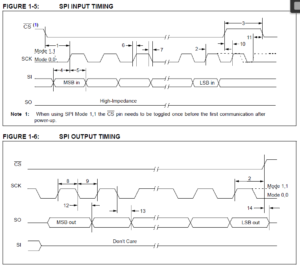
The following is the SPI communication timing:

Here is the list of things to visit in order to successfully get MCP23S17 to work with DK-TM4C123G:
1). Reprogram the Chip Select pin from the SPI controller on the MCU side
From the timing of MCP23S17, it requires the Chip Select (CS) signal to remain low for all data transmission, which has a conflict with TI DK-TM4C123G microcontroller whose SPI controller always pulls up CS line after each byte is sent:

To address this problem, we need to reprogram the SSIxFxx pin as a GPIO pin so that the code can drive it to low for the whole period when all bytes are transmitted.
2) Configure SPI settings
The proper SPI settings (mode, clock rate, data byte width etc) need to be obtained by checking the data sheet of that both SPI master and the target to ensure that they are acceptable for both sides. For DK-TM4C123G and MCP23S17, the following parameters can be used:
- Mode: 0
- Clock Rate: 10MHz
- Data width: 8 bits/byte
3) Determine the data access mode
Since DK-TM4C123G supports either interrupt or polling, you can pick up the most appropriate data access mode based on your application’s design. Generally speaking, using interrupt is the more efficient way to read the data from the target as it won’t waste any CPU cycles. To use it, you would need to:
- Enable the interrupt for SSI controller on the DK-TM4C123G side
- Write your ISR to replace the default ISR for above interrupt
- Configure MCP23S17 to use Interrupt mode
4) Keep MCP23S17 from being reset during normal operation
From your application, you need to program the GPIO connected to the EESET pin of MCP23s17 so that it will always be disabled until the chip needs to be reset
5) Determine the configuration of MCP23S17
Besides the parameters mentioned so far, there are some specific configuration of MCP23S17 that you need to decide, they include the Bank Mode (Separate or operate together), byte mode (byte access or sequential) etc.
Once you have successfully initialize both the DK-TM4C123G and MCP23S17, you can access MCP23S17 by either sending to or reading the data over it. Please note, when reading the data out of MCP23S17, the SSInRx line will start to kick in the bits into the receiver buffer once CS is active (and sending the commands and/or Addr to the target), as a result, you need to discard the first few bytes in the receive buffer based on your Send command in order to retrieve the proper data read from MCP23S17.